 Jonathan Bruneau
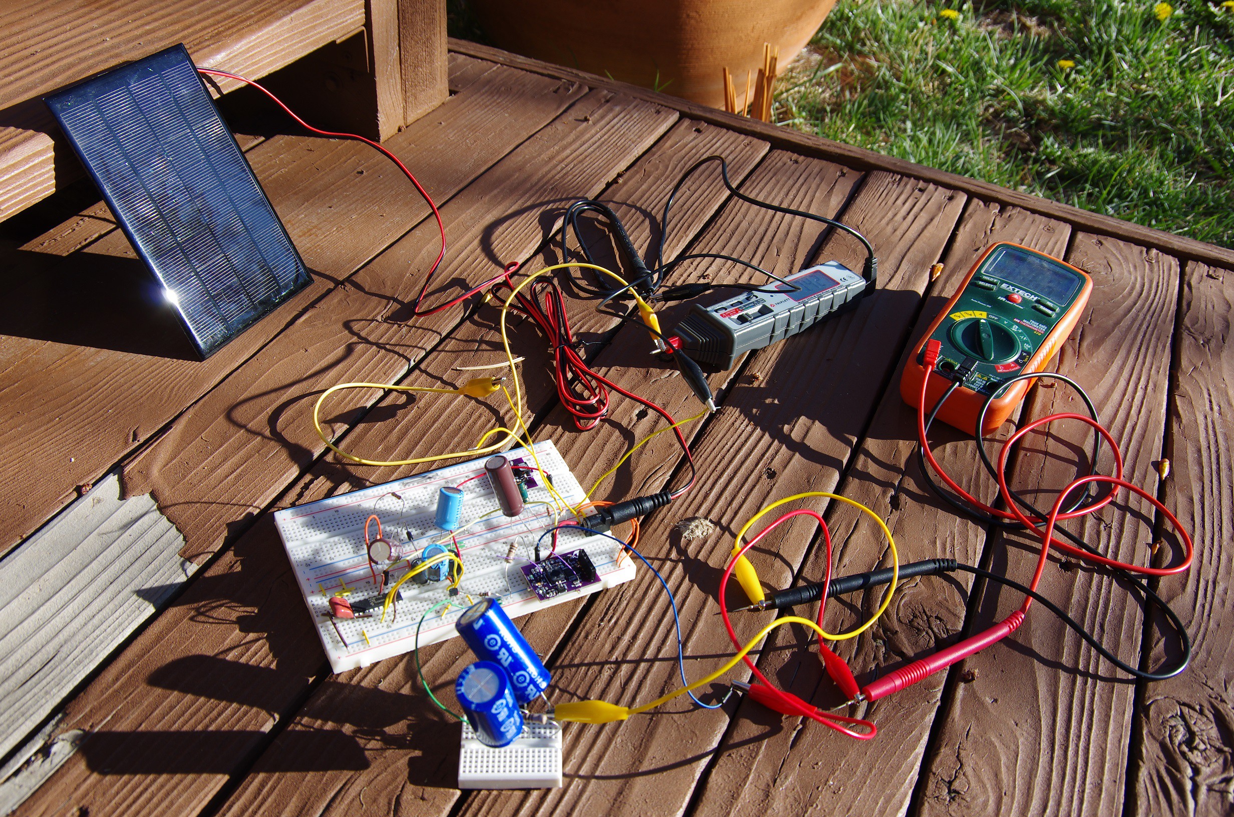
The goal of the project is to provide MPPT functionality at a fraction of the cost of current off-the-shelf solutions. Ideally, the entire MPPT controller would cost $1 and work on 1W panels and above.
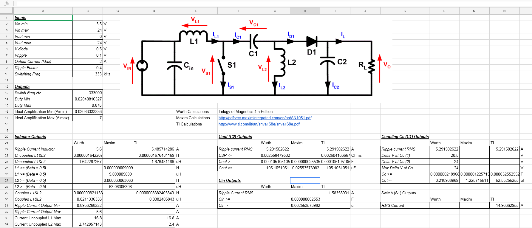
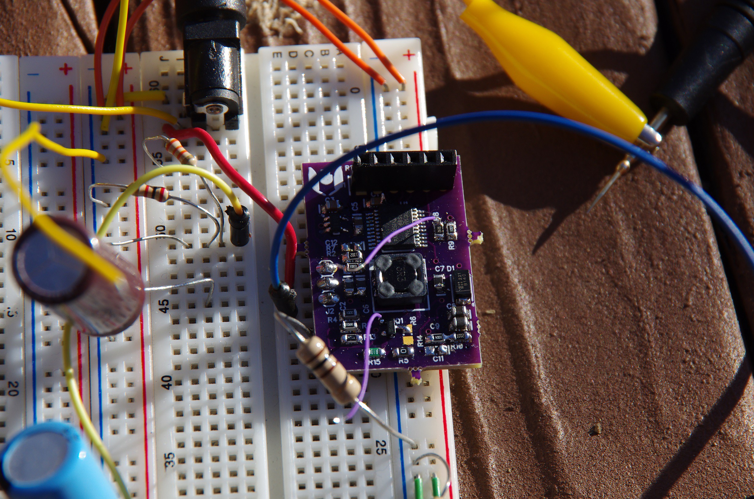
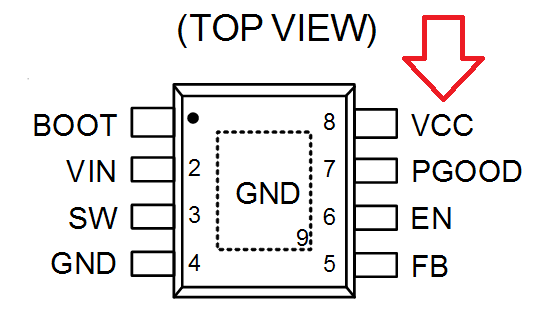
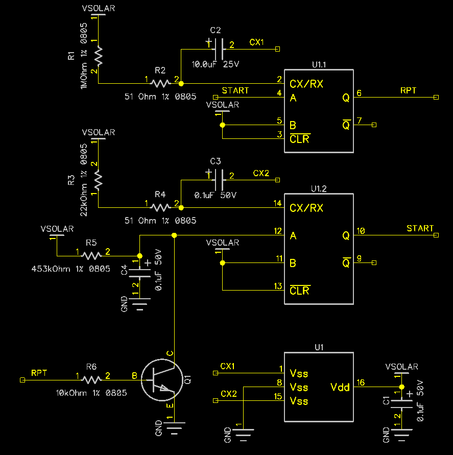
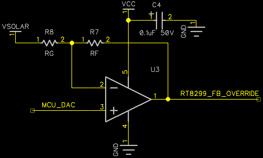
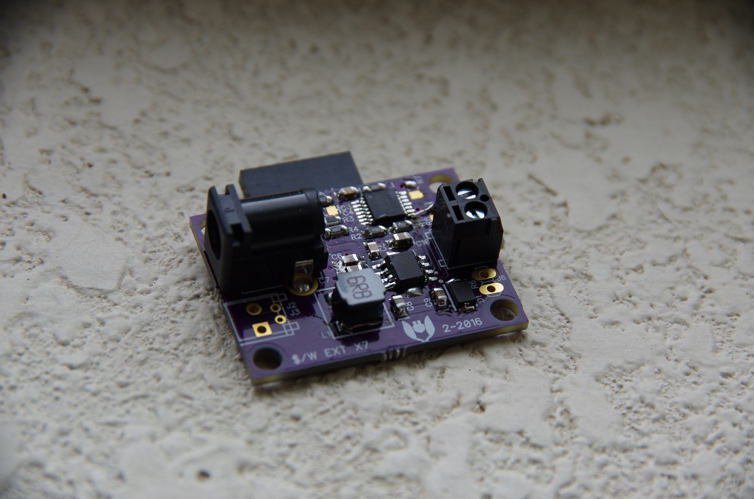
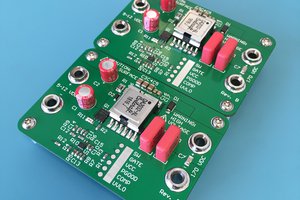
The initial design cost close to $10, but had room to significantly cost reduce. The most up to date design, a large improvement on the original, relies on a tricky hack on override the default behavior of an off-the-shelf buck regulator, and subsequent versions have provided additional cost and performance improvements. The current cost for this circuit is $2.41.
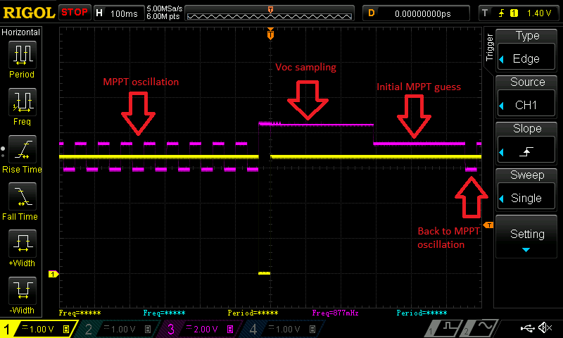
A note about this project. While there already exists hacks to do MPPT on the cheap, those hacks typically rely on some intervention from the user to tune the MPPT to the ideal point. The goal here is to create a true MPPT controller which could be used in 3V solar panels as well as 24V solar panels with no manual tuning.


 Radu Motisan
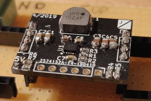
 James Wilson
 Kuba Sunderland-Ober
Any updates you can share?