 Hexastorm
The goal of this project is to develop a laser head for 3D printing or PCB manufacturing which uses a rotating prism and is easy to assemble.
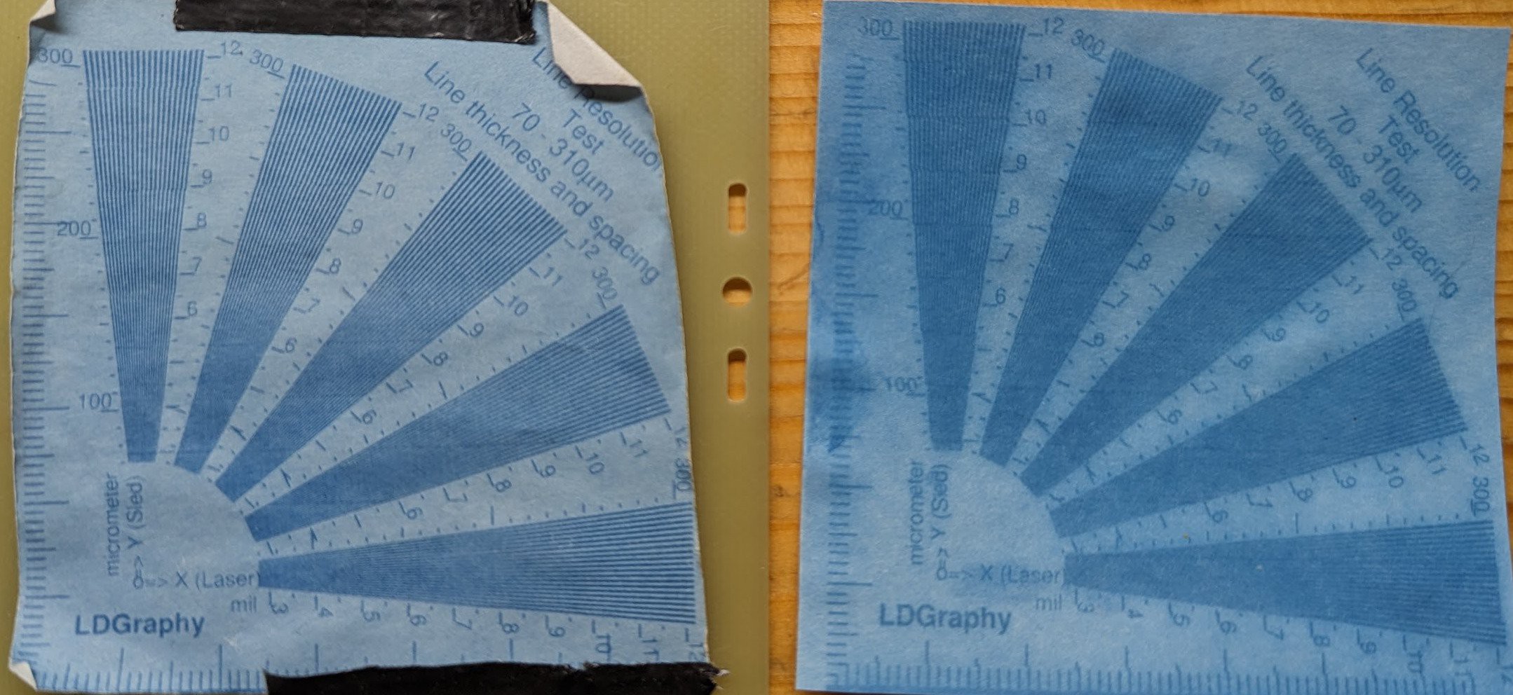
Cyanotype paper is currently used as it can be developed with water.
Specifications
Specifications are determined by exposure onto a camera without lens and OpenCV. More technical details are available in the whitepaper or the business case pitch.
- wavelength: 405 nm
- rotation frequency: up to 21000 RPM, current 2400 RPM
- line speed: up to 34 meters per second @ 21000 RPM
- spot size FWHM: circular, 25 micrometers diameter
- cross scanner error: 40 micrometers (error orthogonal to scan line)
- stabilization accuracy scanning direction: 2.2 micrometers (disabling/enabling scan head)
- jitter: 35 microns (error parallel to scan line)
- duty cycle: 47%
- laser driver frequency: 2.6 MHz
- maximum scan line length: 24 mm
- typical scan line length: 8 mm
- optical power: 500 mW
- facets: prism has 4 facets
- prism dimensions: 30x30x2 mm
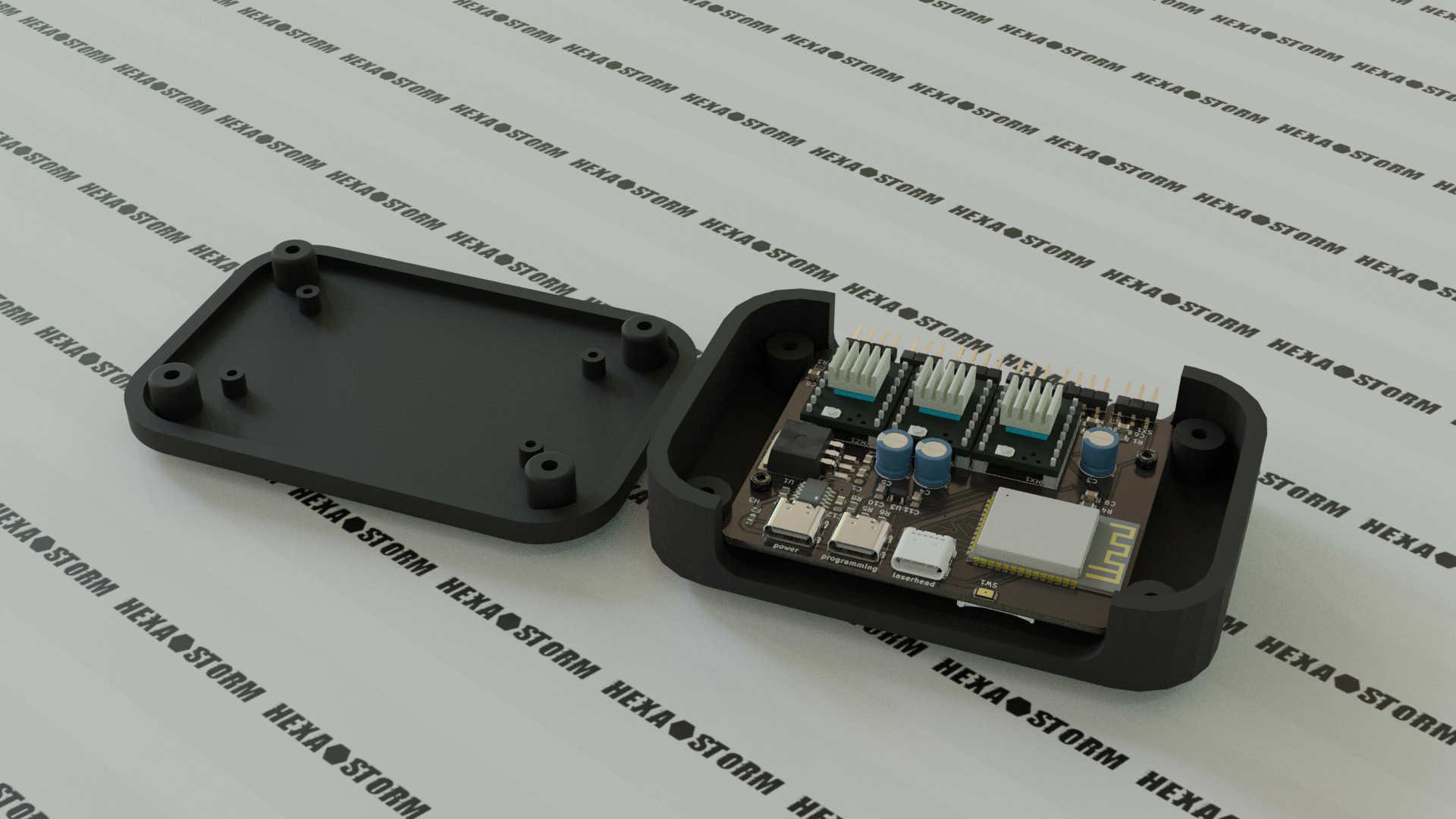
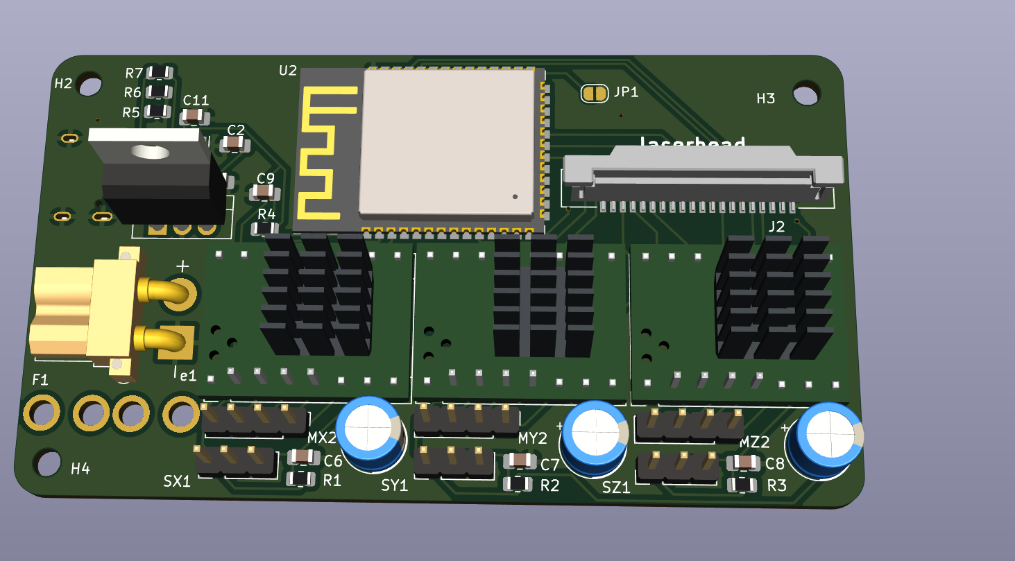
Electronics
- FPGA ICE40UP5K-SG48 with Icestorm toolchain
- Firestarter cape (laser driver, 3x TMC2130 stepper drivers, PWM spindle and fan control)
- Raspberry 4
Status
An image can be exported from Kicad to SVG and converted to instruction for the laserhead.
An exposure result on a printed circuit board with close up is shown below.
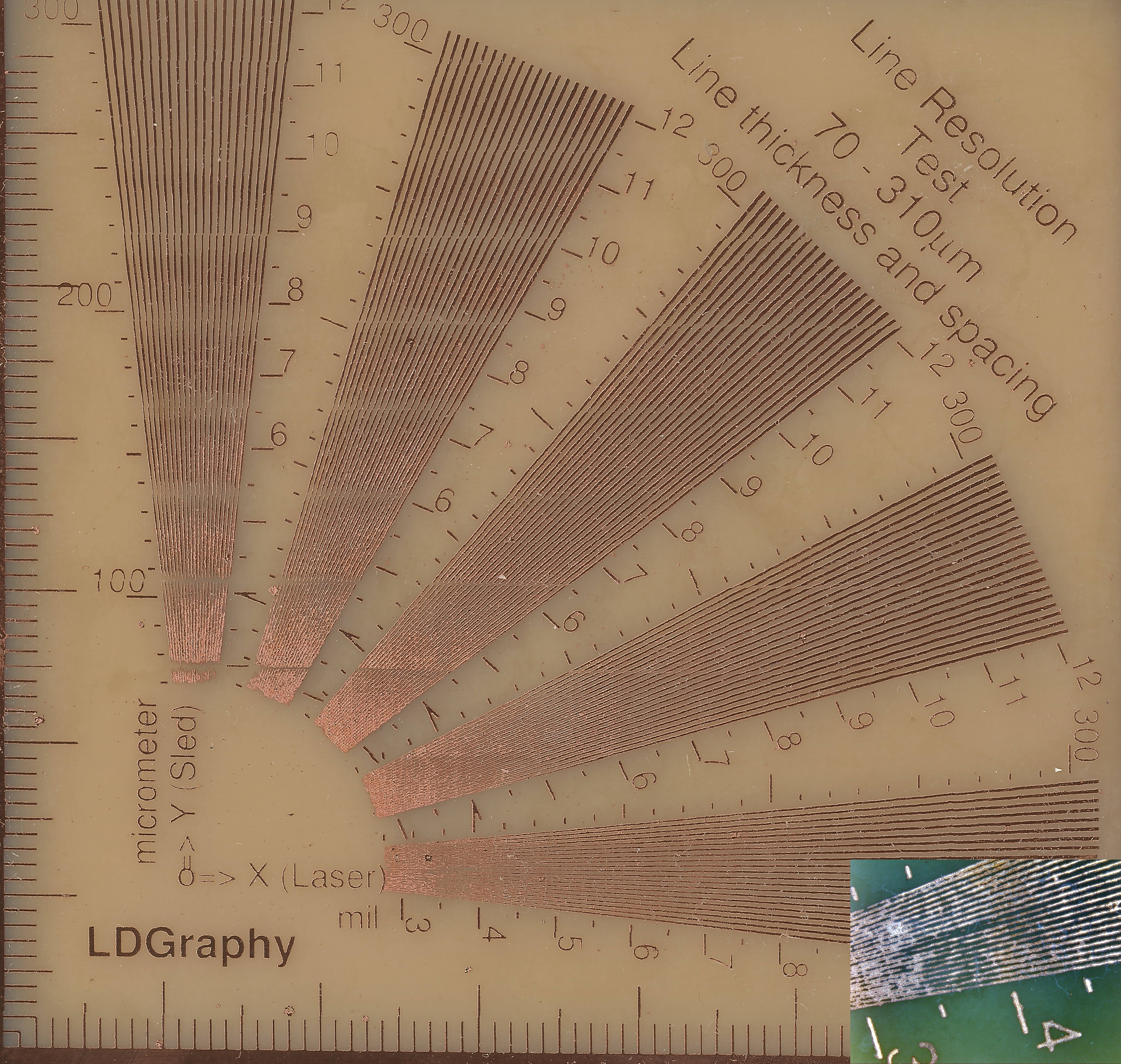
Resolution below 100 microns can be achhieved. Stitching is between lanes is quite good on cyanotype paper but still a bit uneven on PCB. Exposure below is done without cylinder lenses.
An exposure goes as follows (for the result see above).
Acknowledgement
Special thanks go to Henner Zeller for his work on LDGraphy. The electronics and software in this project helped me a lot with constructing the laser scanner, see video.
The initial idea of using a prism for laser scanning originates from Dr. Jacobus Jamar. The first system used a plurality of laser bundles in a thicker prism under an angle. TNO, a research institute of the Netherlands, still pursues this idea, in an entity known as Amsystems.
The current gateware relies on Amaranth HDL and some components from Luna. This is the work of white-quark and ktemkin.
Software
Amaranth HDL gateware for Hexastorm
Optical design
Electronics
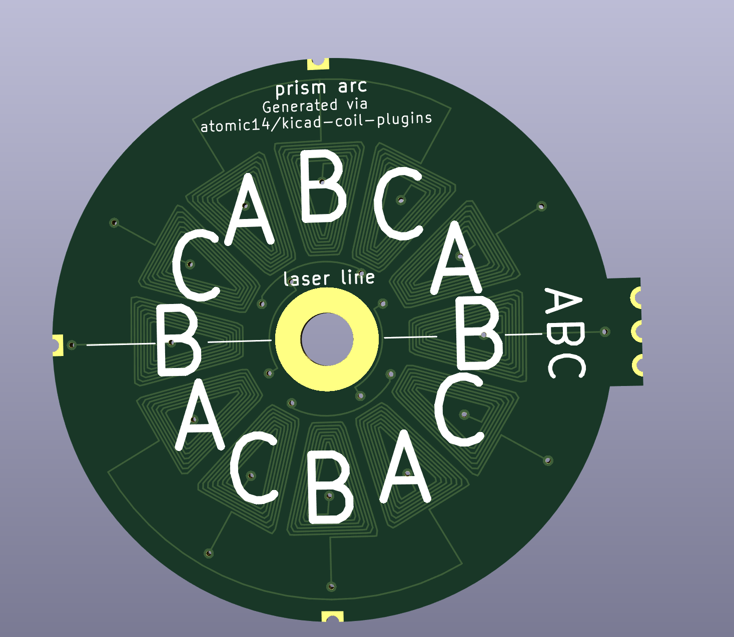
PCB design
Hardware designs
CAD files
Literature Research
White paper @ Reprap
Other Links
Official website

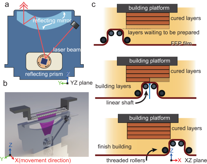 It uses four rollers to apply a new layer to 3d print a part. The article comes with some cool videos and equations describing the mechanism.
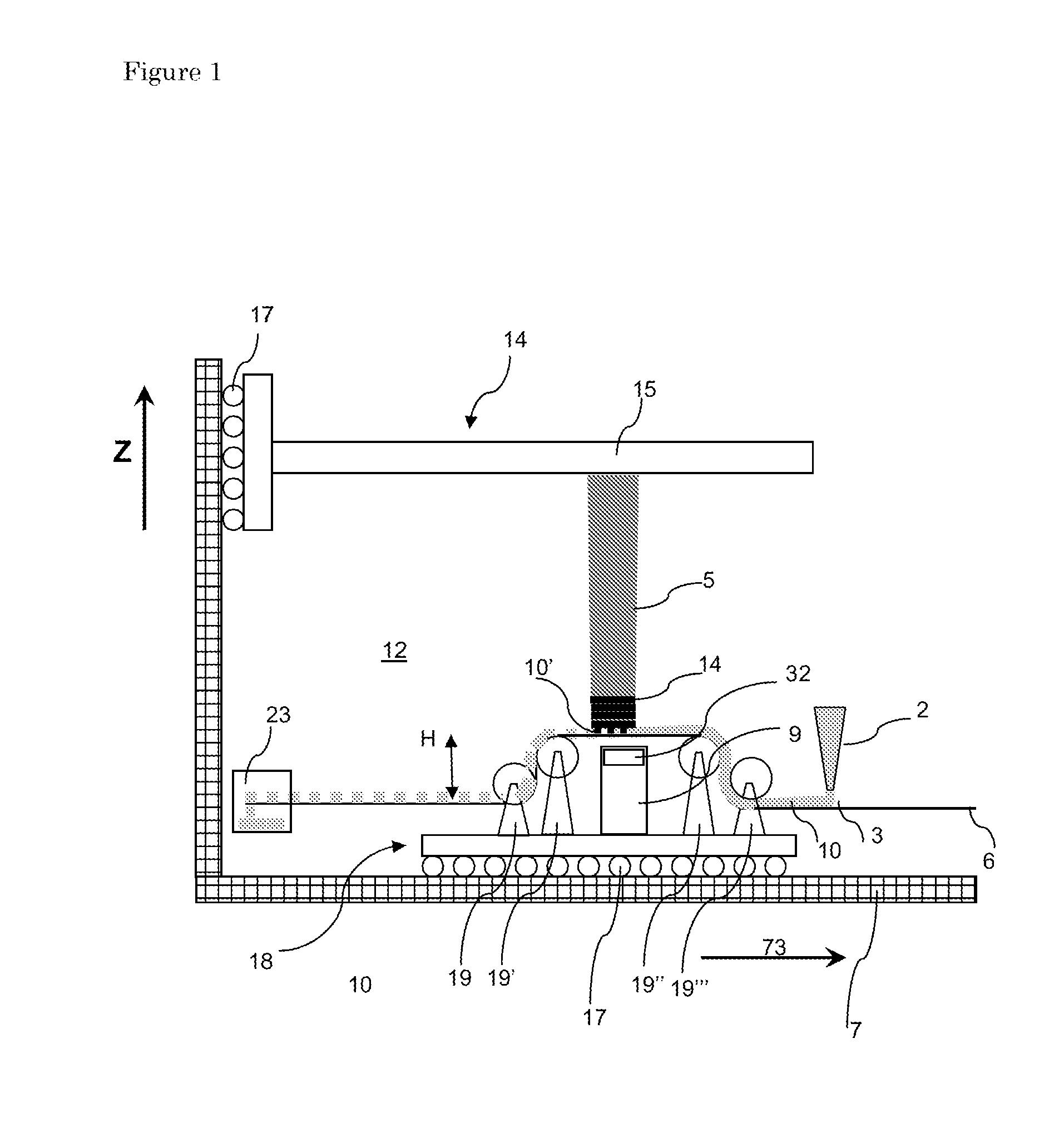


 FabLab München
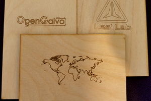
 LesWright
 Ildar Rakhmatulin
Would this work? https://www.edmundoptics.eu/p/20mm-square-uncoated-b270-window/18799/