 Miguel Ayuso Parrilla
General Summary
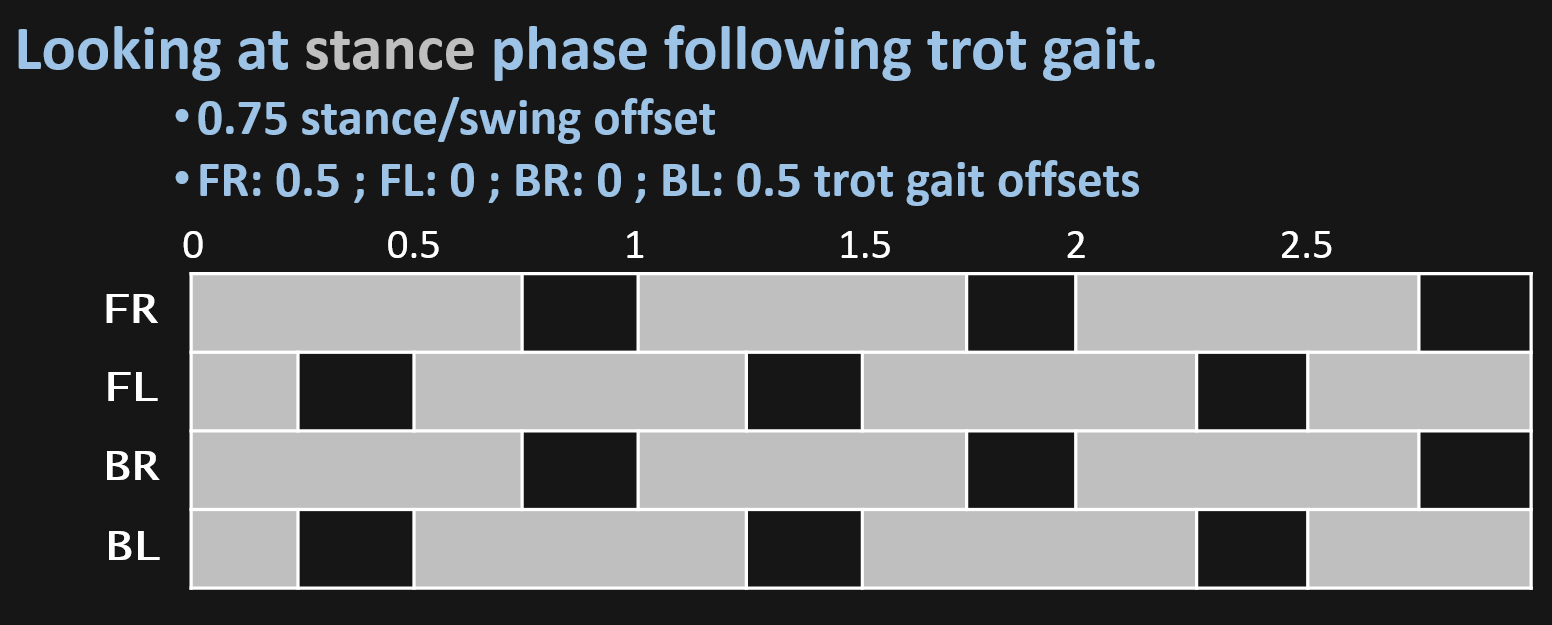
The code which is mostly written by me, using python3 along with some typical libraries for the task, for now implements a walking loop inside a kinematic model, so you can command a pose to the body, as well as feet position and also velocity and directinal commands for the walking loop. Controlled by a ps3 controller via bluetooth.
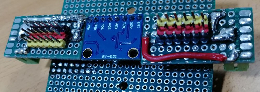
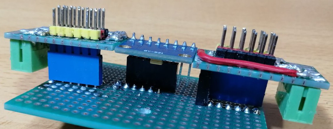
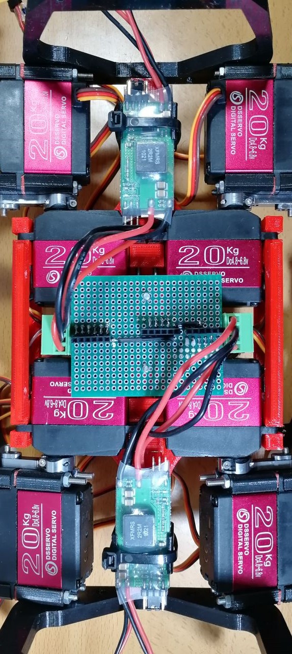
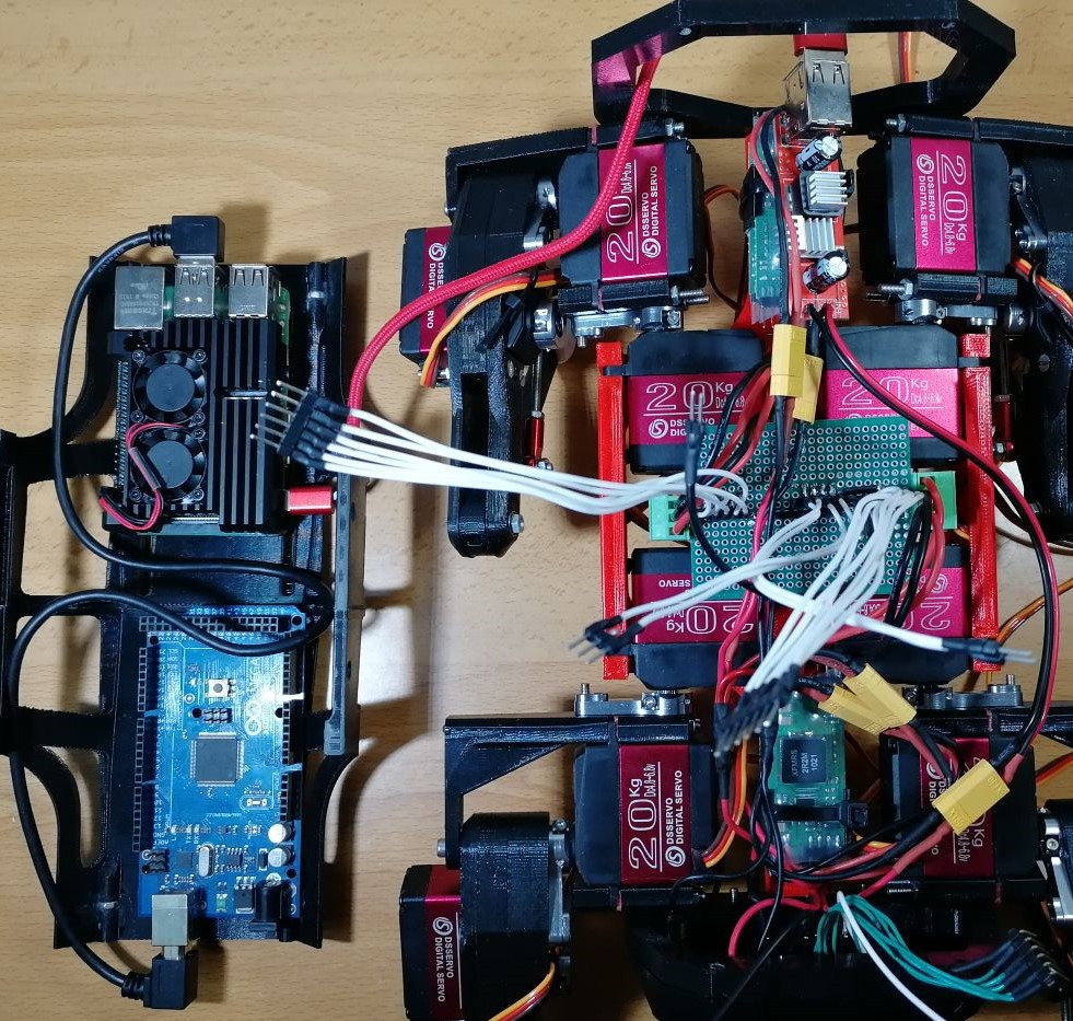
Arduino is used for speed up the reading and writing of signals, so in the future i can add other sensor, as well as position feedback...
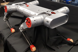
Lets see what this under 500$ robot can do:
Project log index (updated):
- Model and code explanation.
- Robot experiments.
💻💻💻💻 Code of the robot.
📚📚📚📚 Bibliography and readings of the project.
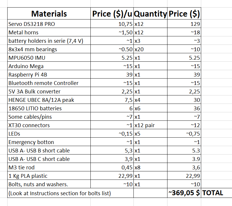
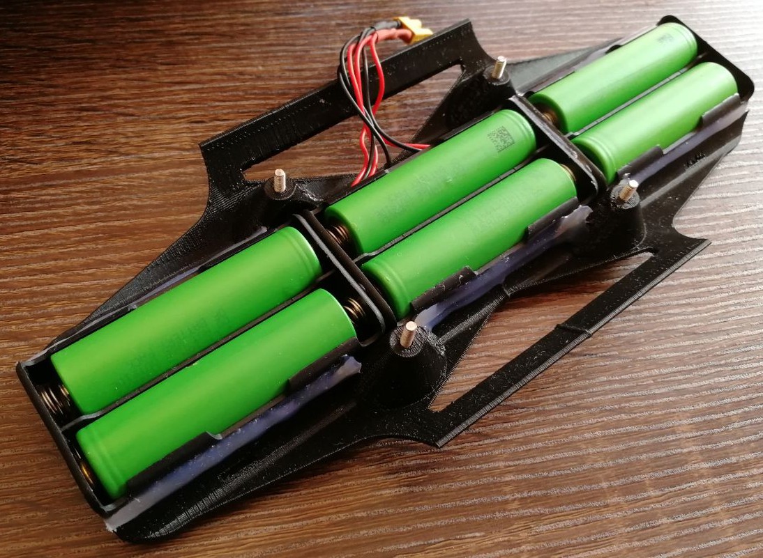
🔨🔨🔨🔨Bill of materials and price.
🏆🏆🏆🏆Makers that built the robot.
Why building a quadruped robot?
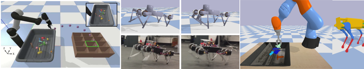
Appart from the interesting control problems that this robot involves, there are lot of interesting tasks this it can carry out and they are beginning to be demonstrated, as we have seen with Spot robot in the 2020 pandemic:
It's obious that there is still lot of work to do, but we are at the time where we can built one of these in our homes and have a very good aproximation of it.
There is a key factor in this robot, it doesn't need roads in orther to operate, so it can reach places that are very hard for a wheeled machine, so these 4-legged robot are ideal for tasks such as surveillance, recognition of areas not passable by vehicles and even rescues in areas with danger of collapse.
Finally, it is clear for now, that my robot isn't able to do those tasks, but for now i am satisfied that the robot walks stable and who knows if in the future it will be able to bring me a beer from the fridge, just by telling to it: 'dog bring me a beer!'
What problems will you face with this robot?
These legged robot have always amazed me, but it was hard to find easy to understand research, as well as a non-trivial mecanical designs plus complex maths. This makes the project hard to achive good results with DIY resources. So i rolled up my slevees and started reading papers from different investigation groups in the subject.
What my project apport to the maker community?
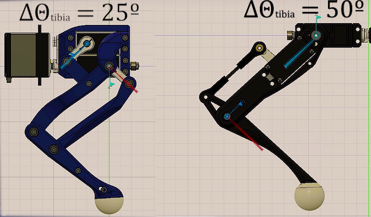
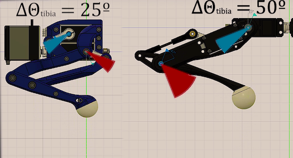
As this project is multidiciplinary, appart from designing my own version of the robot, i focused on its maths, solving different problems related with the movement of the robot, making a very looking forward model which only implements the maths necessary to run the robot, showing how every equation is related with the real robot and givin a general view of it.
This is not the most robust way of building a model, as in real world robots there are lot of additional maths methods in order to pulish the behaviour of the robot, for example, adding interpolation methods would make the robot performs smoother or building an state stimator + filter (kalman state stimator) would let you do very preccise meassurements on the robot and make its movements even more natural.
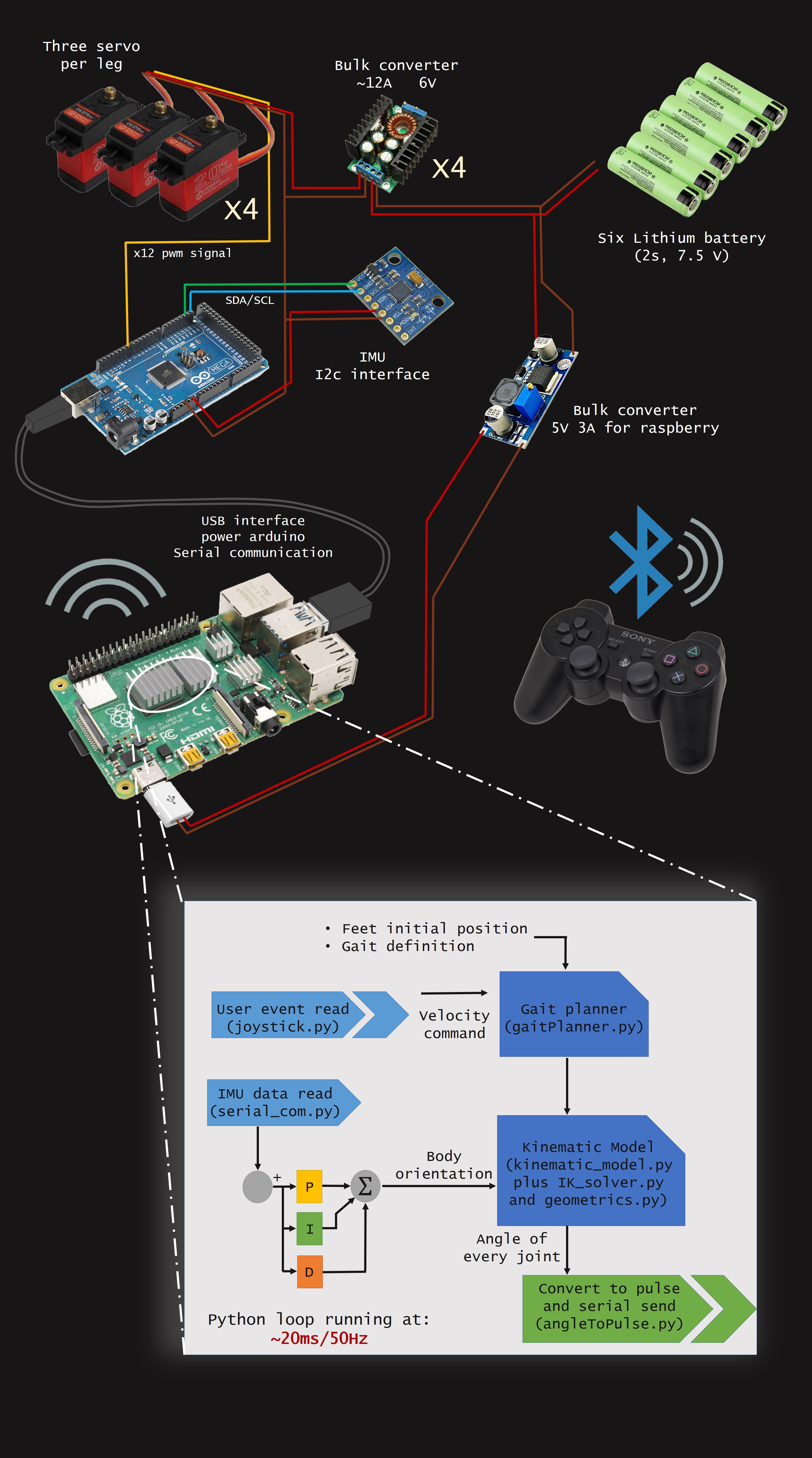
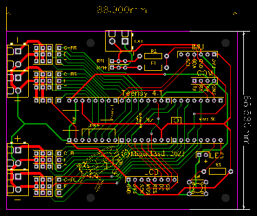
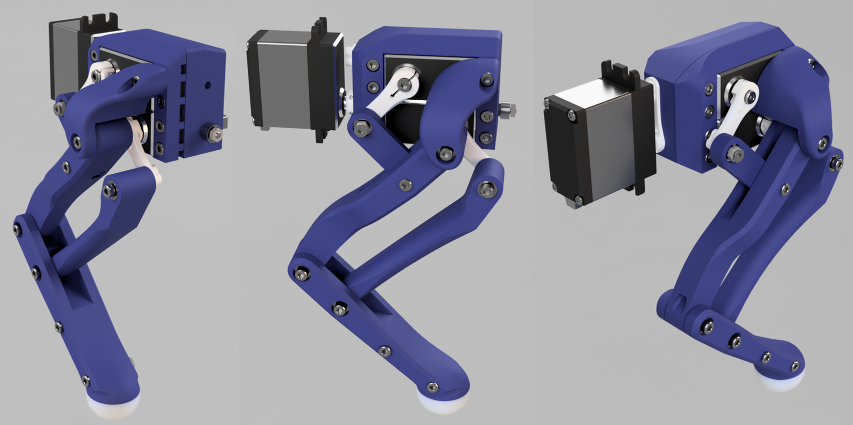
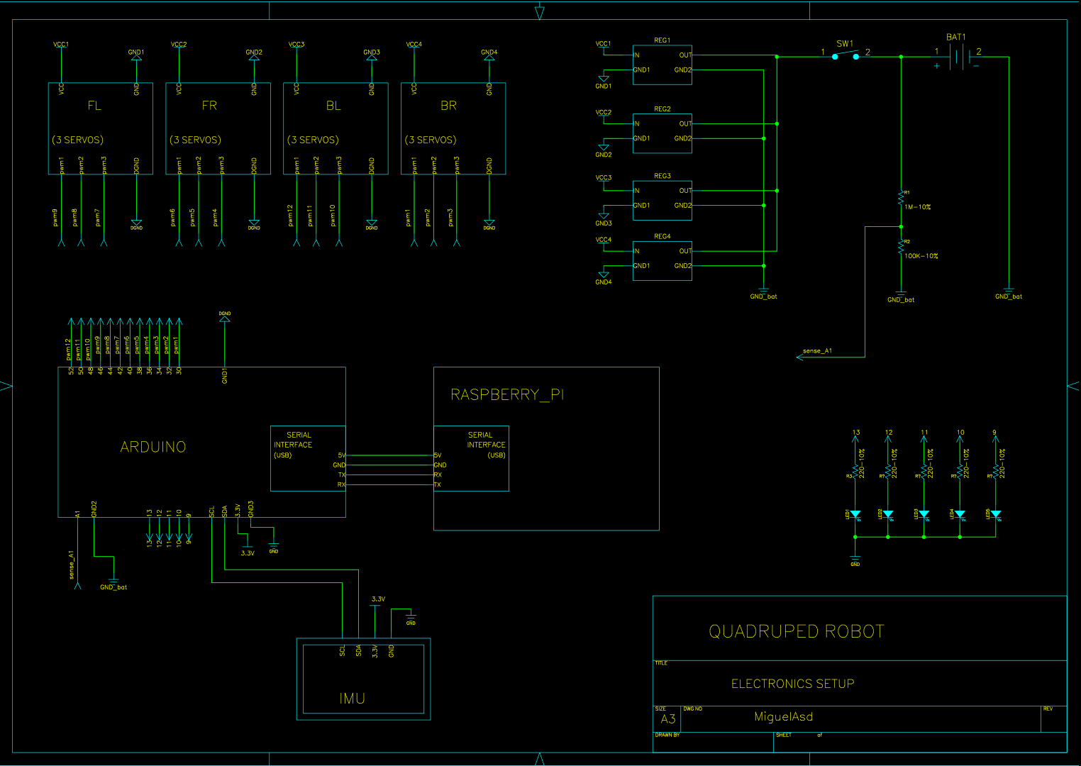
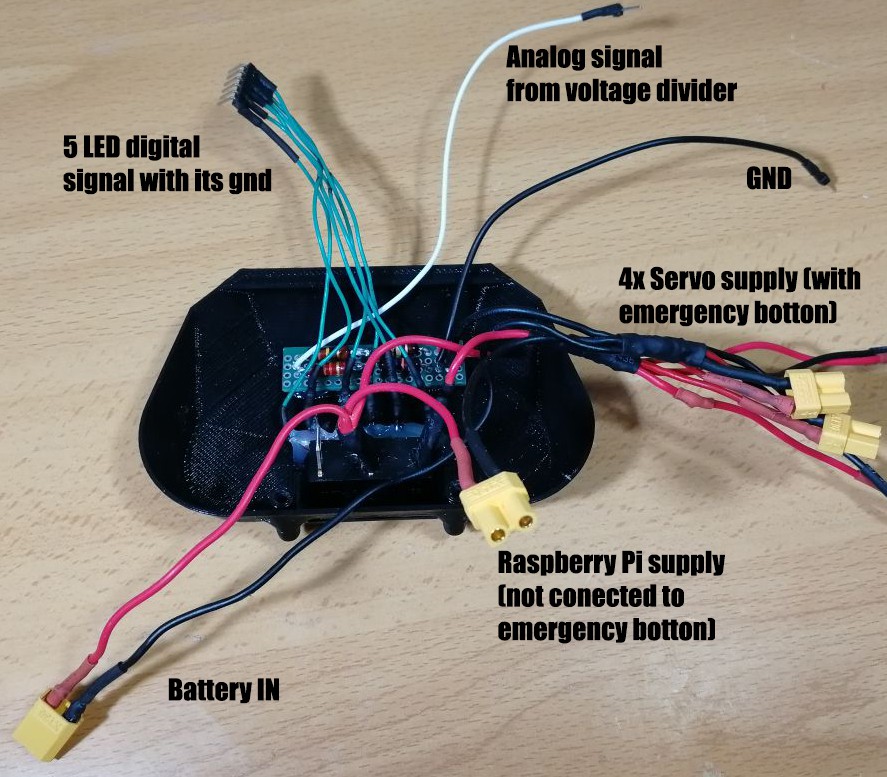
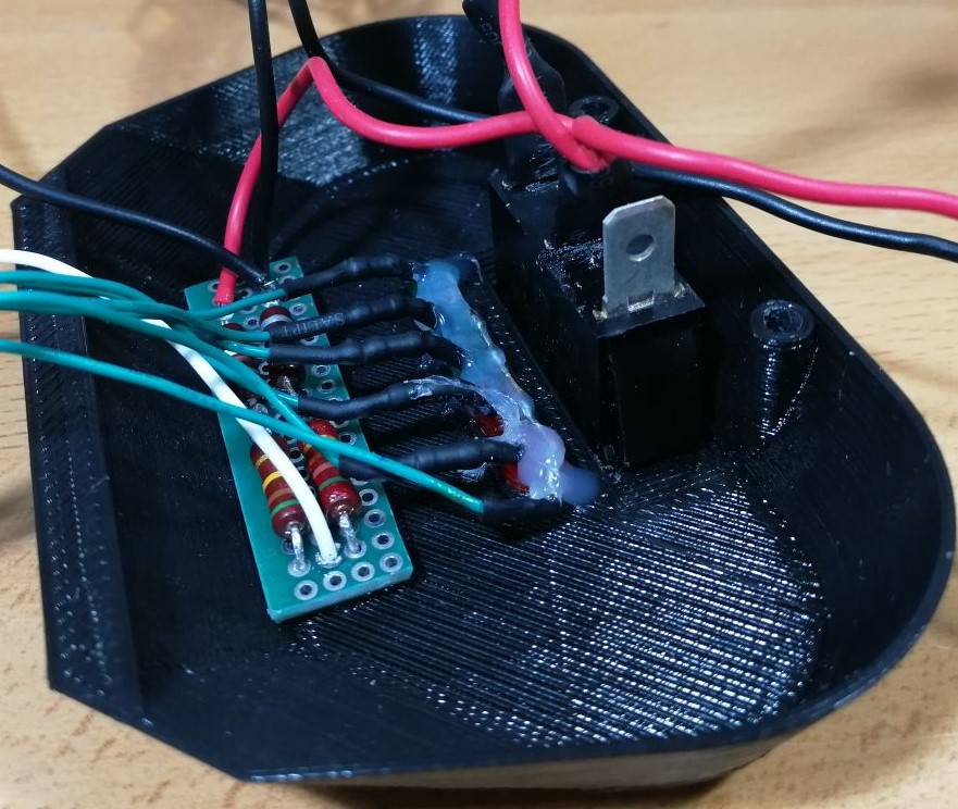
Visual scheme of electronics and model.
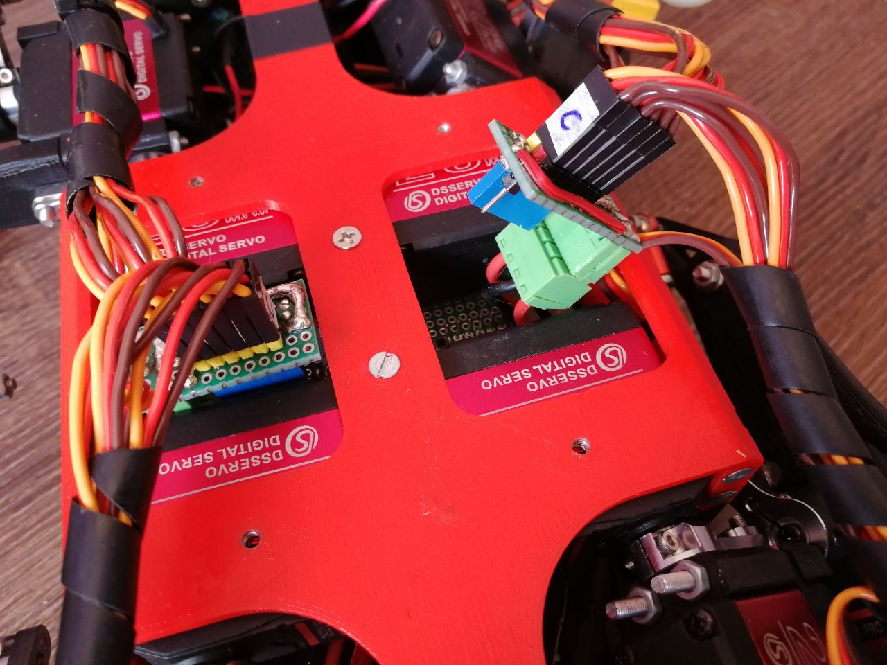
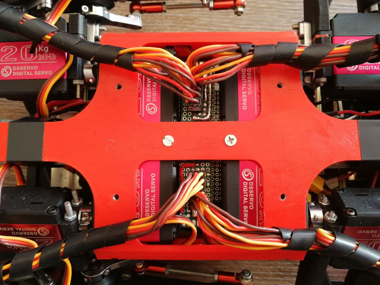
As you can see in the scheme, in this setup i use one bulk converter por 3 servos, with 4 bulk converters in total. This is because each servo drains up to 4A peak.
NOTE: This would not be a rigorous way of wiring, it is just a drawing.
Licensing
This project uses the GPL v3 license for all software related.
This project uses the Attribution-NonCommercial-ShareAlike 4.0 International for all hardware components.
Read more »


 Charles Galambos
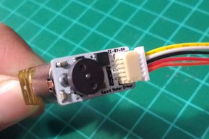
 Danny FR
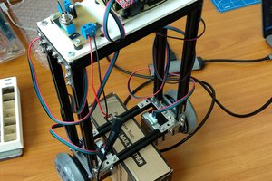
 Sergey Royz
 newdrive
Hi Miguel,
How can you calculated and choose servo? I just saw in this project you shared you reference about that and didn't see how you calculated.