 Yann Guidon / YGDES
After the explorations with #YGREC-РЭС15-bis, I reached several limits and I decided to scale it down as much as possible. And this one will be implemented both with relays and VHDL, since the YGREC8 is a great replacement for Microchip's PICs.
A significant reduction of the register set's size is required so I/O must be managed differently, through specific instructions. The register map is now:
- D1 <= for NOP
- A1
- D2
- A2
- R1
- R2
- R3
- PC <= for INV
The instruction word is shrunk down to 16 bits. It is still reminiscent of the YGREC16 older brother but I had to make clear cuts... The YGREC8 is a 1R1W machine (like x86) instead of the RISCy YGREC16, to remove one field. Speed should be decent, with a pretty short critical datapath, and all the instructions execute in one clock cycle (except the LDCx instructions and computed writes to PC).
The fields have evolved with time (I have tried various locations and sizes). For example:
20171116: The latest evolution of the instruction format has added a 9-bits immediate field address for the I/O instructions.
20180112: Imm9 is now removed again...
20181024: changed the names of some fields
20181101: modified the conditions to change Imm3 into Imm4
20180112: Imm9 back again ! (for speed/latency reasons, no register operand is provided, an indirect IO register is used instead, and having more IO space is more desirable, otherwise only imm4 is available if a register operand is used)
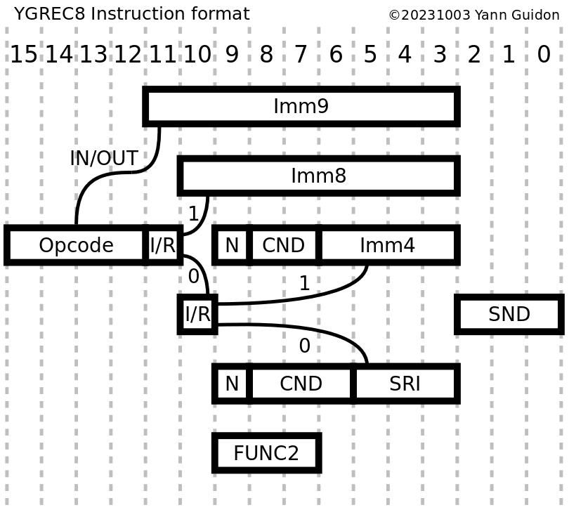
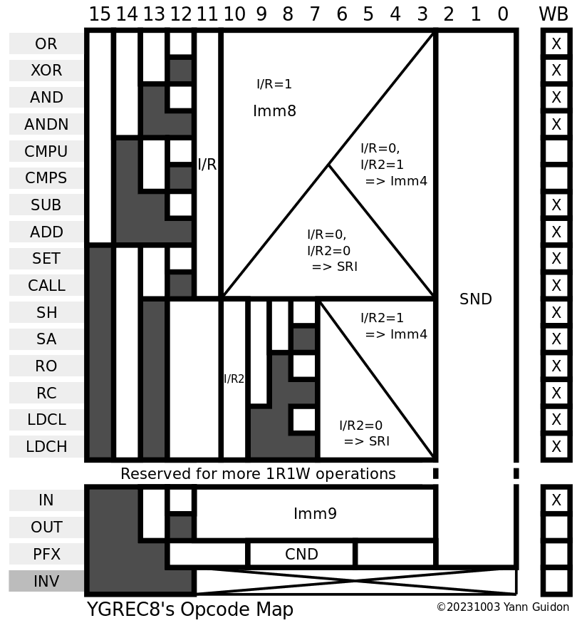
There are 18 useful opcodes (as many as EDSAC plus INV, and the pseudo-opcodes HLT and NOP), and most share two instruction forms : either an IMM8 field, or a source & condition field. The source field can be a register or a short immediate field (4 bits only but essential for conditional short jumps or increments/decrements).
The main opcode field has 4 bits and the following values:
Logic group :
- OR
- XOR
- AND
- ANDN
Arithmetic group:
- CMPU
- CMPS
- SUB
- ADD
Deprecated:
Beware : There is no point to ADD 0, so ADD with short immediate (Imm4) will skip the value 0 and the range is now from -8 to -1 and +1 to +8. (see 17. Basic assembly programming idioms)
Shift group (optional)
- SH/SA direction is sign of shift, I/R(bit9) is Logic/Arithmetic flag.
- RO/RC direction is sign of shift, I/R(bit 9) allows carry to be rotated.
Control group:
- IN,
- OUT (yes, the system is so small that a specific I/O channel system is required, unlike #YGREC16 - YG's 16bits Relay Electric Computer that uses register-mapped I/O)
- LDCL/LDCH
- SET
- CALL (maps to OVL and HLT)
The COND field has 3 bits (for Imm4) or 4 bits, more than YGREC16, so we can add more direct binary input signals. CALL is moved to the opcodes so one more code is available. All conditions can be negated so we have :
- Always
- C (Carry)
- S (Sign, MSB)
- Z (Zero, all bits cleared)
- B0, B1, B2, B3 (for register-register form, we can select 4 bits to test from user-defined sources)
(notice the mnemotechnic trick: ACSZ are in alphabetical order)
Instruction code 0000h should map to NOP, and the NEVER condition, hence ALWAYS is coded as 1.
Instruction code FFFFh should map to INV, which traps or reboots the CPU (through the overlay mechanism): condition is implicitly ALWAYS because it's a IMM8 format.
Overall, it's still orthogonal and very simple to decode, despite the added complexity of dealing with 1R1W code.
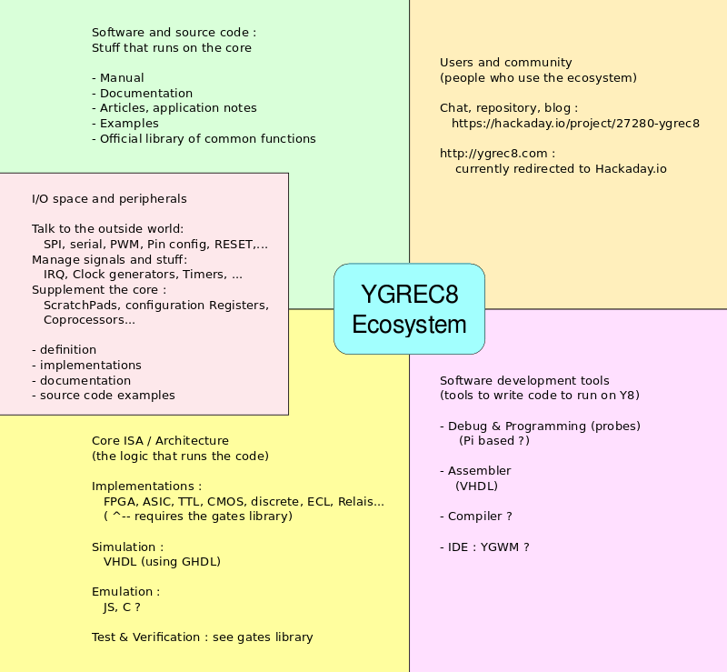
This project is more than an ISA or one implementation : the goal is to become a platform. See log 82. Project organisation
Logs:
1. Honey, I forgot the MOV
2. Small progress
3. Breakpoints !
4. The YGREC debug system
5. YGREC in VHDL, ALU redesign
6. ALU in VHDL, day 2
7. Programming the YGREC8
8. And a shifter, and a register set...
9. I/O registers
10. Timer(s)
11. Structure update
12. Instruction cycle counter
13. First synthesis
14. Coloration syntaxique pour Nano
15. Assembly language and syntax
16. Inspect and control the core
17. Basic assembly programming idioms
18. Constant tables in program space
19. Trap/Interrupt vector table
20. Automated upload of overlays into program memory
21. Making room for another instruction
22. Opcode map
23. Sequencing the core
24. Synchronous Serial Debugging
25. MUX trees
26. Flags, PC and IO ports
27. Binary translation (updated)
28. Even better register set
29. A better relay-based MUX64
30. Register set again
31. Rename that opcode !
32. Register set again again
33. Yet Another Fork
34. What can it run ?
35. More register set layout
36. More VHDL and more gates
37. R7 P&R
38. Program Counter and other considerations
39. Bus names (SRC-SRI, DST/SND)
40. Now faster without the "PC-swap" MUX
41. A diode-less balanced relay amplifier
42. Imm4
43. Data retention times of hysteretic relay latches
44. Assembly syntax
45. Assembly in VHDL works
46. Improved Shuffling Unit
47. Improved ROP2
48. Improved linear power supply
49. Power supply for the register set
50. Mister Bin
51. Another opcode re-organisation
52. High-current germanium diodes
53. More high-current germanium diodes
54. The new disassembler
55. and the new assembler
56. An even better ALU
57. ROP2 reloaded
58. That ALU should be good
59. Netlist and structure of the adder
60. A new unit : the decoder
61. Making Y8 more energy-efficient with a deglitcher
62. Floorplanning
63. GHDL in a docker container
64. Scheduling
65. Scheduling (2)
66. Control-gating the register set
67. A little note
68. How to divide the register set's power consumption by about 5
69. Census of the gates
70. The nexus
71. A new assembler panel
72. Wiring the new assembler panel
73. More wiring of the new assembler panel
74. Interlocked switches galore !
75. ASM panel dimensions
76. Updated wiring of the new assembler panel
77. The disassembler panel
78. More assembler panel stuff
79. Diode (P)ROM wasn't built in a day
80. A Diode (P)ROM was (almost) built in a day
81. Need help with RES60 / РЭС60 relays
82. Project organisation
83. Progress with the assembler panel
84. More progress with the assembler panel
85. Assembler panel working
86. Sensing relays
87. Decoding the register names
88. Register name display : OK
89. Condition codes : decoder & display
90. RES64 > RES15 (somewhat)
91. A "hub" for the instructions
92. A new system for the register set
93. A proper reset for the double-coil latch
94. Bubble-pushing the ROP2
95. Pushing more bubbles, now the carry-lookahead adder
96. New decoder for the ALU
97. Core state machine
98. And now, capacitors !
99. Magnetic interferences
100. An unexpected but welcome tool
101. Adder with Falstad
102. ROP2 with Falstad
103. NAND3
104. Bitslice
105. Re-NANDifying the CLA
106. FSM update
107. Choosing the gates
108. INC8 ASICified
109. Gray counter
110. The art of large MUXes
111. The first half of the TAP
112. Design of a TAP : the SIPO Controller
113. The TAP's bits counter
114. The TAP selector
115. The TAP is coming together
116. TAP summary & protocol
117. Trap on instruction
118. The TAP's eXecute module
119. The TAP crosses 3 clock domains !
120. TAP v.2
121. Synthesis checks
122. Updated Gray Counter
123. TAP v.2 : where it's going
124. TAP timing & simulation
125. TAP v.2's selector
126. TAP pins
127. A tale of Flip-Flops
128. More (virtual) relays
129. Counters strike !
130. Add with carry : the macro
131. Towards a better assembler, still in VHDL, sans Lex & Yacc
132. Undecided overlay options
133. Status 20211114
134. jumping back and forth, and carry
135. The YGREC8 Assembler
136. Tri-mode TAP
137. counters
138. A little explanation
139. Carry on
140. A semi-decent output port
141. My first prefix opcode...
142. More room for some opcodes
143. System overview
144. ENTRY: Another pseudo-instruction from CALL corner cases
145. The status byte
146. Updated number syntax
147. System registers in the I/O Reg space
148. Opcode space statistics
149. Assembler v2023!
150. Code golf: Snake edition!
151. Code Golf Snake: part deux
.
.
.