 Arya
AryaSubscribe to the project newsletter - to get weekly news and be notified about crowdfunding!
Read previous newsletter editions
Latest newsletter editions:
- Hackaday Prize, documentation, tutorials and Pi Zero hacks
- Building&testing phones, UI facelift and leaflets
- Mod boards, project priorities and building a new batch
- Modern phones are getting more and more complicated and hardware-packed. Unfortunately, that means they're becoming less modifiable and repairable.
- Phones are getting more and more integrated. Unfortunately, that means more and more possibilities for manufacturers to lock them down without allowing us to modify them.
- More and more software&hardware is kept closed-sourced. That means it's harder to learn, experiment and customize your phone.
The factors I've listed (integration, complexity and closed-source) are necessary in the world we're living in, with all the advances in engineering, competition between companies, as well as laws in different countries.
However, what if we could have a phone free from those constraints?
So, ZeroPhone project was born. Nowadays, we should be able to assemble a phone from easily available parts, using cheap boards that run Linux, and we should be able to adjust it to our needs - unlike as it is with modern phones, when we have to adjust ourselves to suit the workflow that the phone offers. With ZeroPhone, hackers can finally have smartphones that are going to work for them and not against them, people with special needs will be able to have to have custom-tailored phones, and people that want to protect their privacy will have a phone that respects that.
Technical challenges are: developing PCBs that'd be reasonably feature-packed, but with easily sourceable components that could be soldered without special tools, as well as developing mobile phone software that'd be open, high-quality and highly modifiable to suit any needs people might have. However, much bigger challenges are - building a community of people experimenting with ZeroPhone platform, keeping ZeroPhone open-source and independent of any harmful influences, and experimenting with new ways of integrating smartphones in our lives without having to lose privacy in return.
Features:
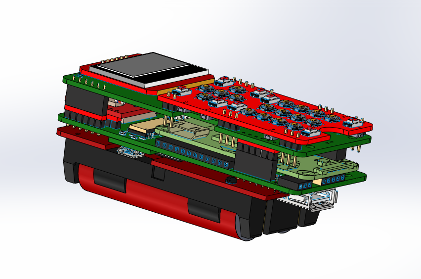
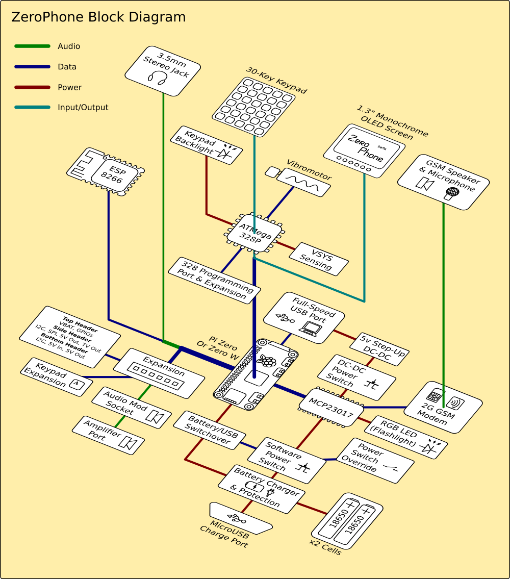
- Raspberry Pi Zero in a PCB sandwich
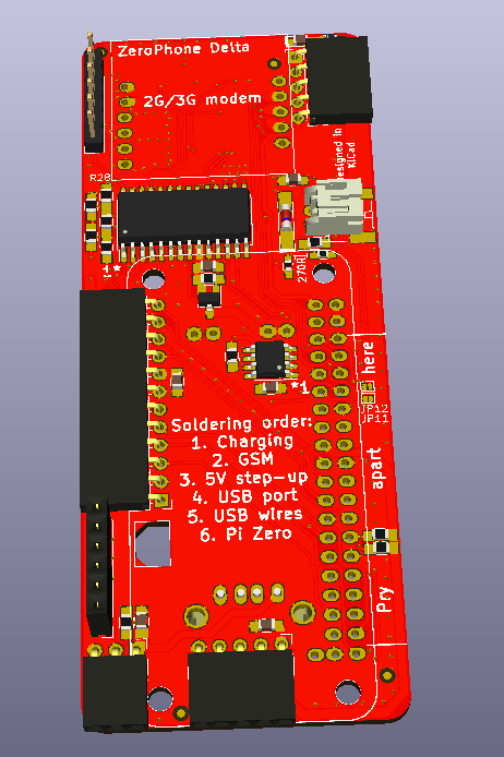
- No proprietary connectors, hard-to-get parts or chips that are tricky to solder
- All the specifications for making this phone yourself will be available
- Python as the main language for developing apps (aiming to add other languages later)
- UI toolkit that makes app development quicker and easier
- Numeric keypad, 1.3" 128x64 monochrome OLED screen (also supports other screens)
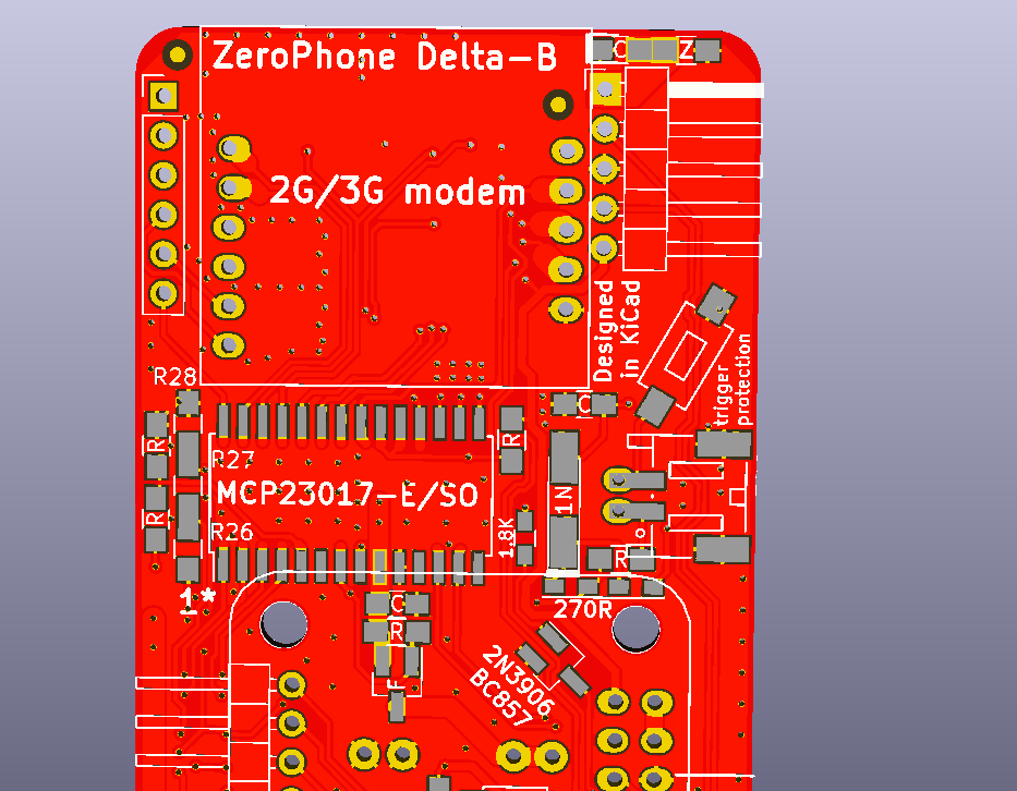
- 2G modem for phone functions, can be replaced with a 3G modem
- WiFi (using an ESP8266), HDMI and audio outputs, a free full-sized USB host port and a MicroUSB port for charging
- GPIO expansion headers for hardware addons and customization
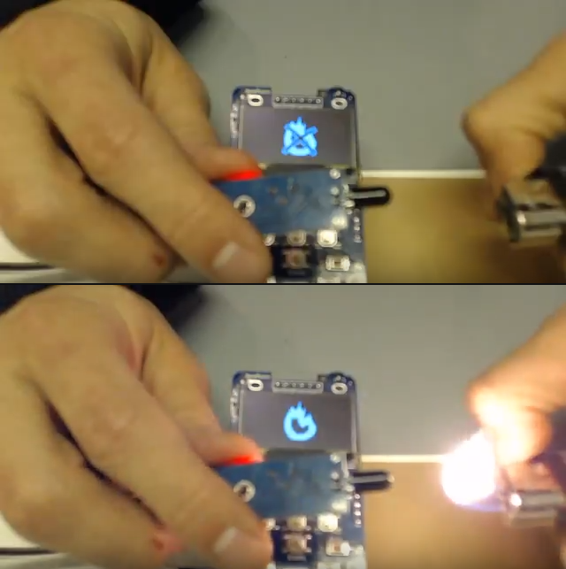
- RGB LED and vibromotor - for notifications
Interesting articles:
- Developing a simple app - UPnP/SSDP scan
- Mod boards and expansion ports
- How to actually make money from ZeroPhones? (a.k.a business plan)
- Hardware switches, and audio-based tracking that some companies do
- Why do we need Open-Source phones?
- Explaining choices behind the project
- Why not a large display (with a touchscreen)?
- What about the apps?
- Making the phone accessible and using Chinese breakouts
- On volatility of Chinese breakouts; "production-ready" ZeroPhones
- Mod boards and expansion ports
- Challenge: Zero W Bluetooth problem
- On testing of ZeroPhones
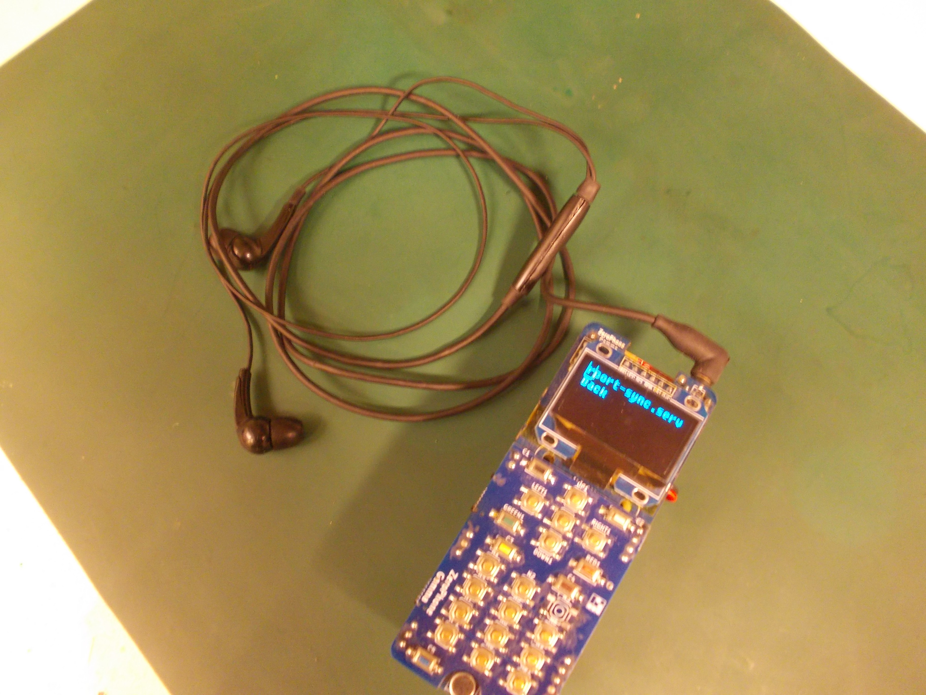
- How I use my ZeroPhone (part 1)
- A guide on powering Pi Zero directly from LiIon batteries
- An in-depth explanation of a simple GPIO app
- Why I'm currently using 18650 batteries
- Making ZeroPhone work as an actual phone
Licensing:
#pyLCI fork used for ZeroPhone is licensed under Apache License
ZeroPhone PCB files and keypad controller firmware are licensed under GPL v3
Read more »

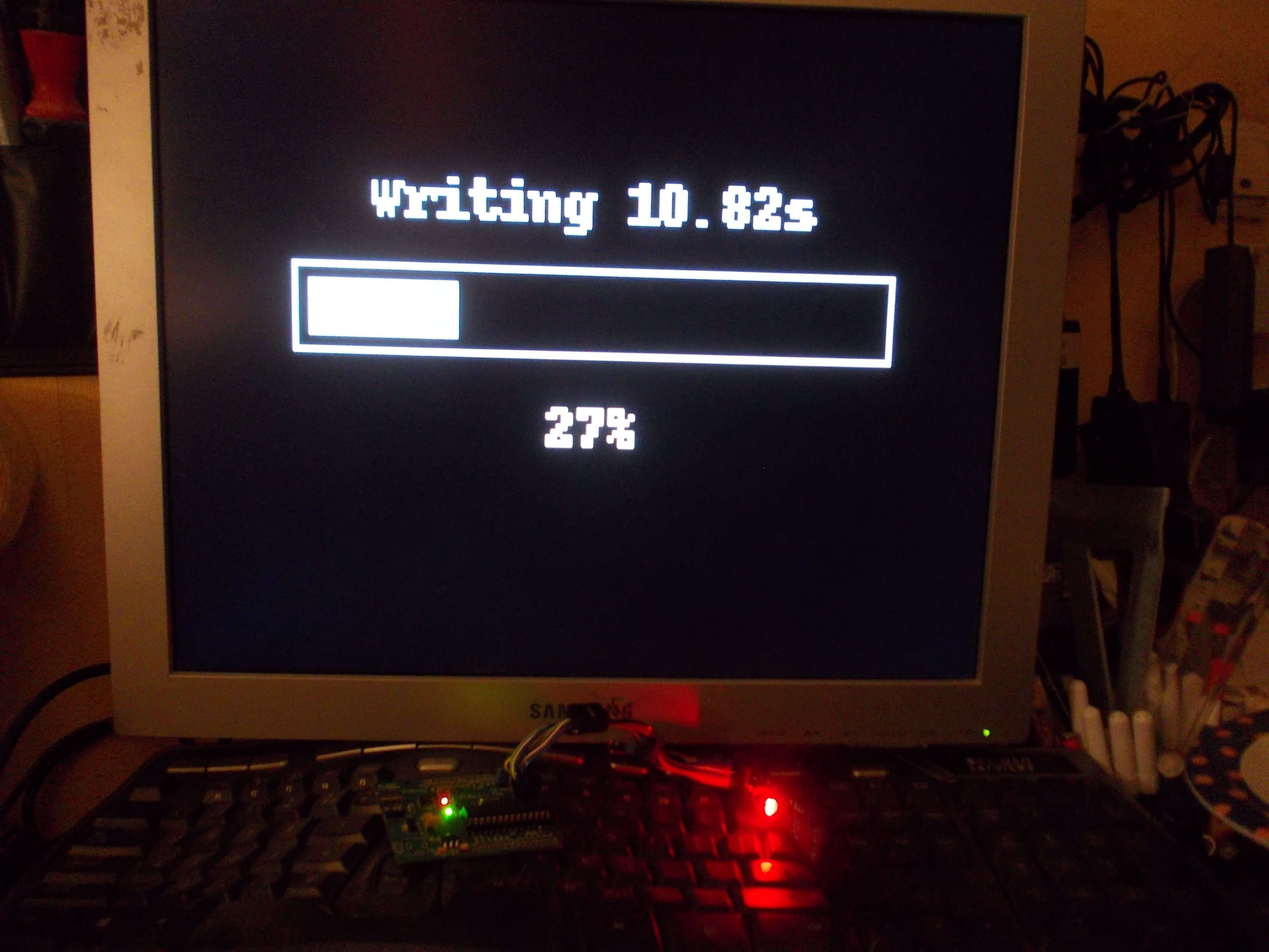
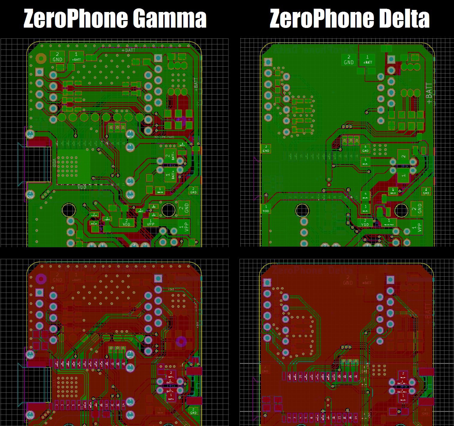
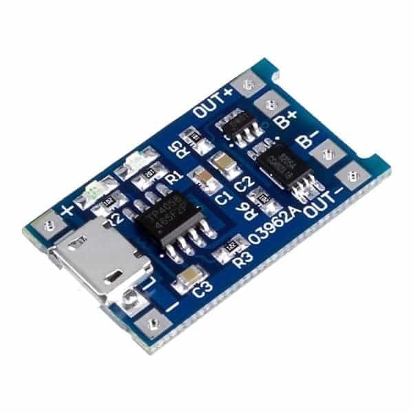
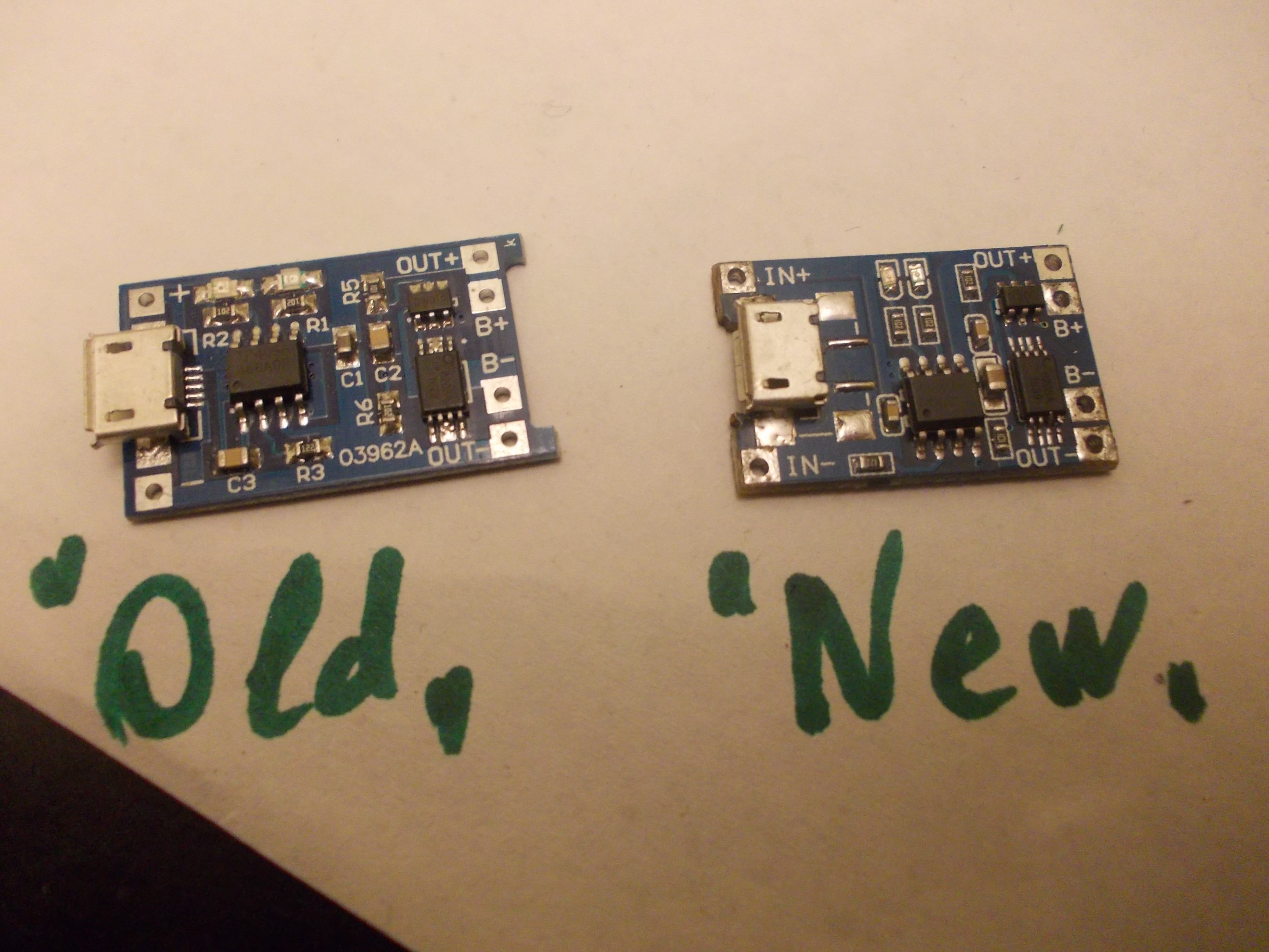
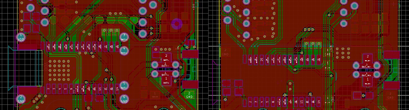 During the manufacturing, we'll need to find a way to either find a reliable source for these modules, or to manufacture our own (I've already reverse-engineered the schematics and the PCB, thankfully, and I'm asking for manufacturing quotes) - as a backup plan in case the commercial modules are no longer suitable for us. I've also tried understanding the problem by comparing "old" and "new" modules - I've checked the schematic and it's the same (the boards are slightly different, but the changes are minimal), so my guess is that the "new" modules are using cheaper components, which causes the failures. But, just in case, I'm going to see if there's a way for us to source these boards reliably.
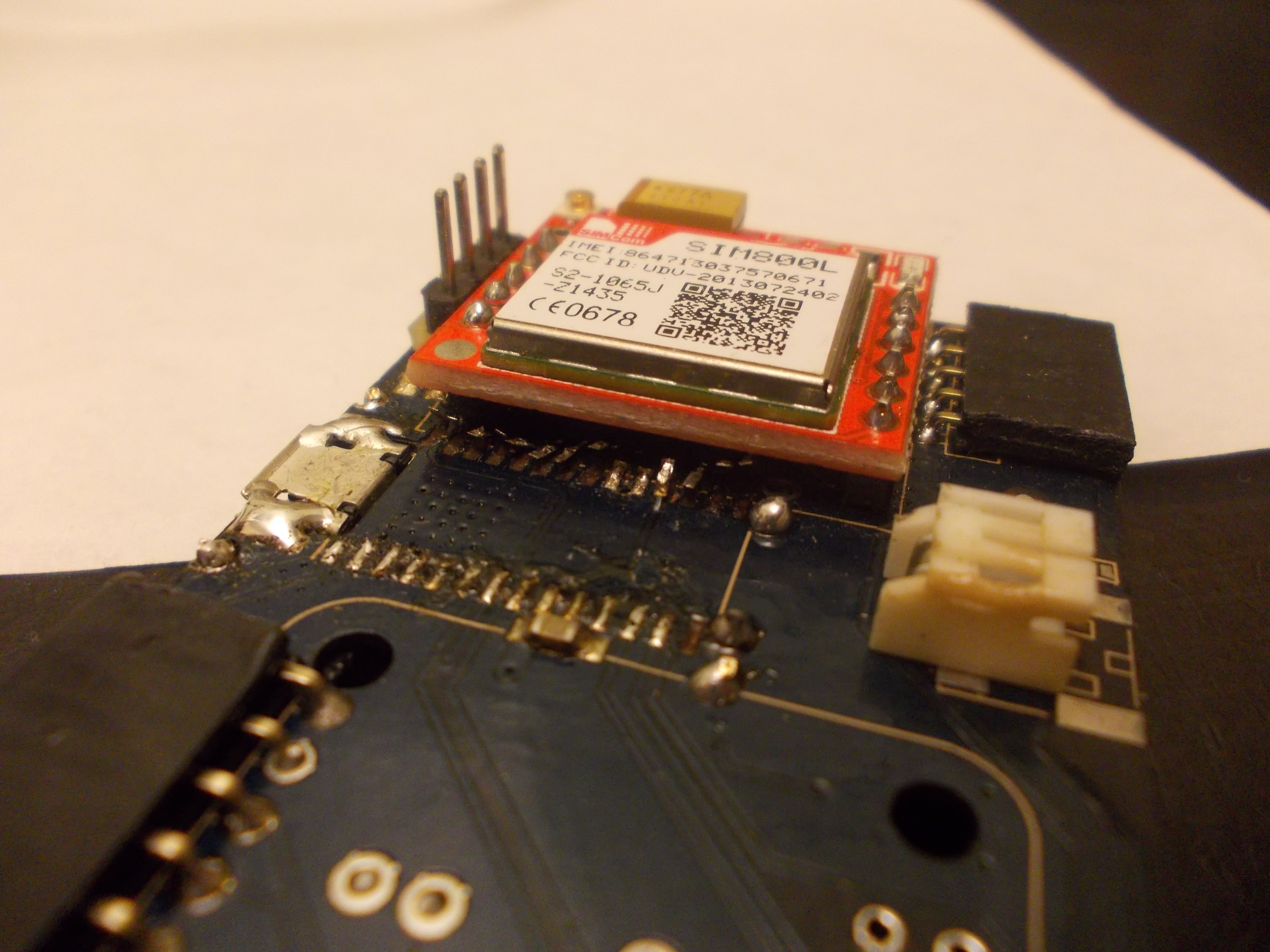


 John Adams
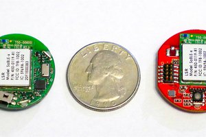
 Trey German
 Casual Cyborg
 Pavel Zhovner
Can the screen be made bigger and run Android or CopperHeadOS? If no then why not?